
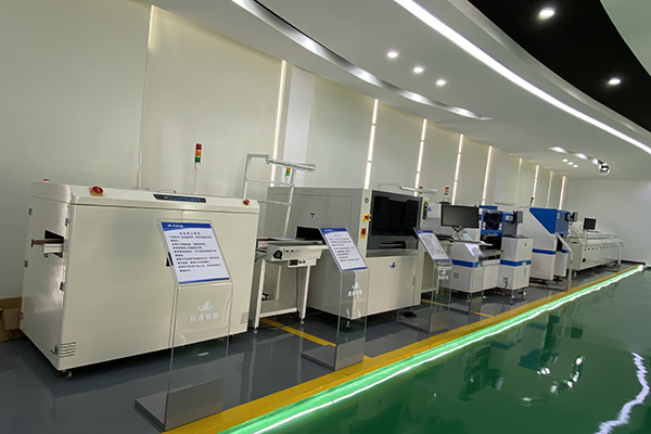
The surface mount process is the production flow used to assemble most modern electronic circuit boards. It connects solder paste printing, component placement, reflow soldering, inspection, and process feedback into one repeatable system.
For buyers planning a new line, the surface mount process answers a practical question: what happens before a PCB becomes a reliable assembled board? The answer helps them compare equipment, factory layout, quality control, and supplier capability.
What Is the Surface Mount Process?
The surface mount process places electronic components directly onto printed circuit boards. It is widely used for LED lighting, consumer electronics, power products, appliances, and industrial control boards.
First, the line prepares the PCB. Then, it prints solder paste, places components, and completes soldering in a reflow oven. Finally, the factory inspects the board and uses production data to improve the next batch.
Step 1: Solder Paste Printing
The process begins with solder paste printing. A stencil transfers solder paste onto the PCB pads. Accurate printing is important because many SMT defects begin at this stage.
Several factors affect print quality. These include stencil design, paste condition, board support, squeegee pressure, printing speed, and alignment. Therefore, operators should check these settings before mass production begins.
For fine-pitch devices, LED boards, and high-density assemblies, solder paste inspection can measure paste volume. As a result, teams can correct printing issues before components are mounted.
Step 2: Pick-and-Place Mounting
Next, the SMT machine picks components from feeders or trays. It then places them onto the printed solder paste.
Feeder accuracy, nozzle selection, vision recognition, placement speed, and board support all affect the result. A high-speed SMT pick and place machine helps manufacturers maintain accurate and stable mounting.
However, speed alone is not enough. A good SMT solution should match the buyer’s real component packages, PCB size, product mix, and output target. Stable mounting is more valuable than a headline speed that cannot be maintained during mixed production.
Step 3: Reflow Soldering
After placement, the PCB enters the reflow oven. The oven heats the board through a controlled temperature profile. This melts the solder paste and forms solder joints.
Temperature control is especially important for LED products, power modules, and dense PCB assemblies. An unsuitable profile can damage components or create weak solder joints. Therefore, factories should verify the profile for each board type and component package.
Step 4: AOI Inspection and Feedback
After reflow, AOI inspection checks placement quality. It can identify polarity errors, missing parts, offset components, solder bridges, and other visible defects.
More importantly, AOI data should be used as process feedback. For example, repeated placement errors may indicate a feeder, nozzle, or program problem. Teams can then correct the cause instead of relying only on final repair.
A complete ETON turnkey SMT production line can combine printing, placement, reflow, conveyors, and inspection equipment into one connected workflow.
How to Plan an SMT Line
Before selecting equipment, buyers should prepare PCB drawings, component lists, panel layouts, daily output targets, and available factory space. They should also consider product changeover frequency and future capacity needs.
The best line is not always the fastest configuration. Instead, it should balance accuracy, capacity, flexibility, quality control, and maintenance needs.
For more information about SMT equipment and factory capabilities, visit the ETON Automation official website.